Tutorials:Creating An End Table In Blender 2.5 Part 2
Contents |
Introduction
This tutorial is part 1 in a series of tutorials which will take you through the process of creating an end table for The Sims 3 in Blender 3D. The series will cover the basics of cloning, meshing, UV mapping, and texturing an object and getting it in the game.
What You Will Need(for the whole series):
- Blender 3D 2.5
- Blender 2.5 TS3 Tools
- DXTBmp
- the latest QA version of S3OC
- The latest QA verison of S3PE
- TextureTweaker
This tutorial will be based on the setup described in this tutorial. I strongly advise doing it proceeding.
| cmo says: If it seems like I'm doing something a different way than I stated in a previous step(i.e using a shortcut instead of a menu), it is because I'm trying to show you different ways to do things, so you can see what works best for you. |
Duplicating For A Low Poly Mesh
Step 1
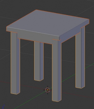
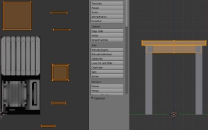
First we have to make a low poly version of mesh. Right-click the tabletop to select it. Then hold SHIFT and right-click the legs. Both parts should now be outlined in orange(one darker than the other).
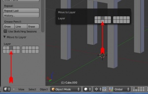
Press SHIFT+D(to duplicate what is selected) then immediately press ESC(to cancel moving th duplication). Now press M and click the 3rd box in the popup to move the duplicate to the 3rd layer. We will do more to that mesh later.
Getting the Original Multiplier
Now that we have the mesh done, we need to unwrap it so we can apply textures to it. This consists of taking apart the mesh and laying it out in a 2D space. In Blender, this is done in in the UV/Image editor. But first we need to get the multiplier image from our pakcage.
Step 2
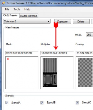
Start TextureTweaker and go to File->Open and open your package in your project folder. Under Multiplier, click in the box above the image(with the numbers in it) to open the Image editor.
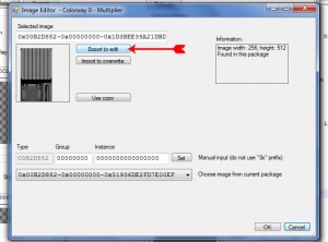
Then click Export to edit, navigate to your project folder, name the file 'multiplier.dds', and click Save. Close the Image editor and then the TextureTweaker.
Step 3
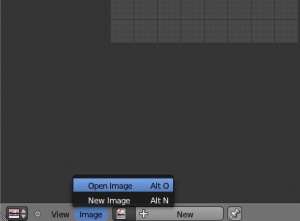
Back in Blender, at the bottom of the UV/Image editor, click Image->Open.
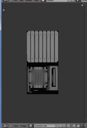
Navigate to your project folder and open the multiplier.dds image.
UV Unwrapping: the Legs
Step 4
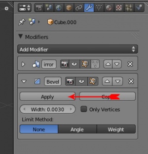
We'll start with the legs. First we have to apply the Bevel modifier we put on the leg in part 1. In the 3D view, right-click the legs to select them. In the Property Editor, click the Modifier button(the one with the wrench). In the Bevel modifier, click the Apply button.
| cmo says: Modifiers don't make permanent changes to the mesh until the are applied. Normally, you would apply the first modifier in the stack first, because you can get unexpected results if you don't. But in this case it's okay. |
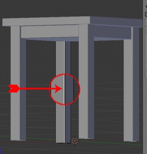
Press TAB to go into Edit mode. While pressing middle mouse button, rotate the view around until you can see the inner corner of the leg.
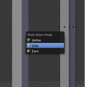
Press CTRL+TAB, then select Edge in the Mesh Select Mode that pops up, select Edge. this will allow you to select the lines between the vertices(edges).
Right-click on the one of the edges that makes the inner corner of the leg(it will turn white).
Step 5
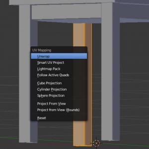
Now go to Mesh->Vertices->Rip(or press V) then press ESC. What this does is split this edge into two. Now when we unwrap it it will lay flat. Now press A to select all the faces, press U and select Unwrap.
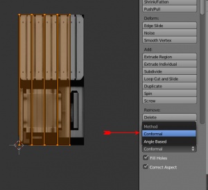
If you don't have the Tool shelf visible, press T to view it. At the bottom of it, you should see some Unwrap options. Change the method to conformal.
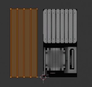
With your cursor in the UV/Image editor, press the NUMPAD minus sign to zoom out a bit. Now press G and move unwrapped leg off of the image, until we know where we want ot put it.
Step 6
Tab back into Object mode, and apply the Mirror modifier. Now all the legs will be actual meshes and mapped to the same spot.
UV Unwrapping: the Top
Step 7
Right-click on the tabletop, and apply it's Bevel modifier. Tab into Edit mode, and change to Face select mode(CTRL+TAB and select Vertex). Press NUMPAD 1 to go to Front view. Then press A until everything is selected.
Press U and select Reset. At the bottom of the UV/Image editor, click the button with the picture with a folded corner and select multiplier.dds. This assigns the UV to this image. Now press A to deselect everything.
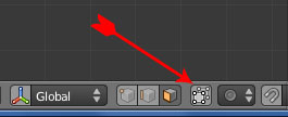
At the bottom of the 3D viewport, next to the Select mode buttons, there is a button with a cube with dots on the corners. This is the Limit Selection to Visible button. This allows you to select only what you see, so back faces won't be selected. We don't want that(it's enabled by default), so click it to disable it.
Step 8
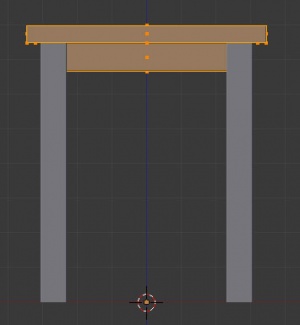
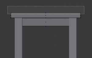
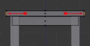
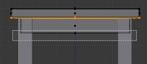
Press B to box select, and click and drag a box around the top three dots to select the top face and it's beveled edges. Press Y to split the edges, separating what we have selected.
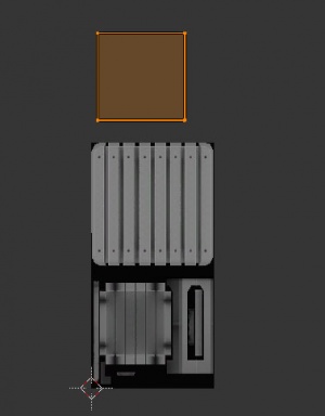
Press U and select Unwrap and change the method to Conformal again. In the UV/Image editor, press R(rotate) and type '45' to rotate the top 45 degrees. Press G and move it up and off of the image.
Step 9
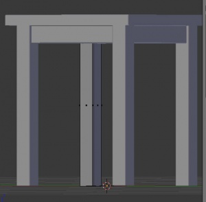
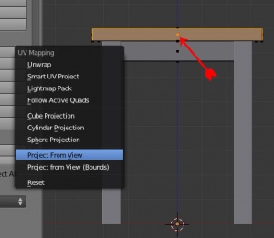
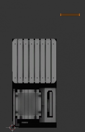
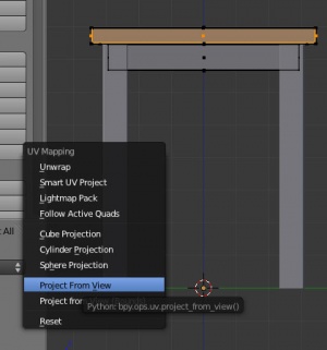
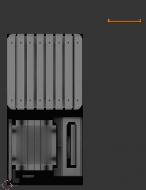
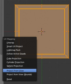
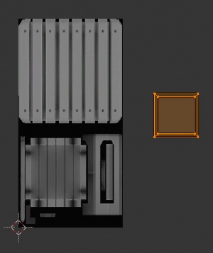
Press A in the 3d viewport to deselect everything. Box select(B) the middle dot to select the front and back sides. Press Y so split it, then unwrap, this time choosing Project from View. Press G in the UV/Image editor and move it up and to the right of the image.
| cmo says: Th
e reason it looks like only one side has been unwrapped is because the sides are mapped on top of each other. Project from view unwraps the mesh based on the view in the 3d view port. Since the sides are identical, they can share part of the map and save space.
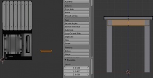
Deselect everything in the 3D viewport again. Box select the middle dots on the left and right sides. Go to side view(View->Right or NUMPAD 3), press Y to split, then unwrap using Project from view.
In the UV/Image editor, press G and move the sides somewhere under the other sides.
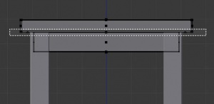
Step 10Deselect everything in the 3D viewport again. Now box select all the dots along the bottom of the top.
Then box select all the dots along the very bottom of the table. Press Y to split them.
Now go to bottom view(View->Bottom or CTRL+NUMPAD 7) and unwrap using Project from view. In the UV/Image editor, press G and move the bottom somewhere to the right.
Step 11Now all we have left is the remaining sides. Go back to front view, and use step 9 to split and unwrap those sides. Move them off the image as well.
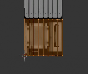
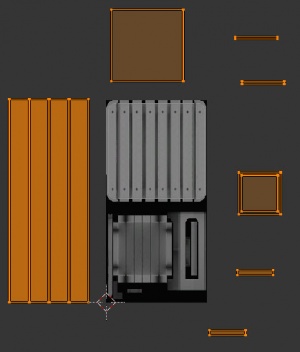
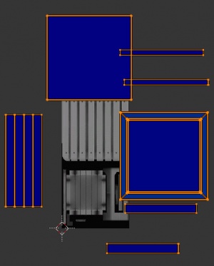
Arranging the MapStep 12Now, if you select everything in the 3D viewport, you will see all the parts in the UV/Image editor.
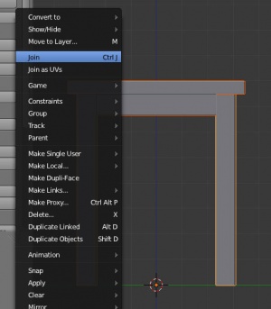
Now go into Object mode, and SHIFT+right-click on the legs. Go to Object->Join(or CTRL+J) to join the two meshes together. Go in to Edit mode again and select everything to see the layout in the UV/Image editor.
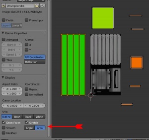
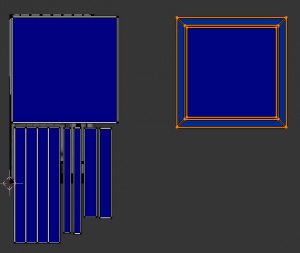
Step 13One problem we have with islands(the separate UV pieces) is that they are not sized correctly. With your cursor in the UV/Image editor, press N to bring up the Properties panel. Scroll down in this panel until you get to the Display section. Check the box next to Stretch and click the Area button.
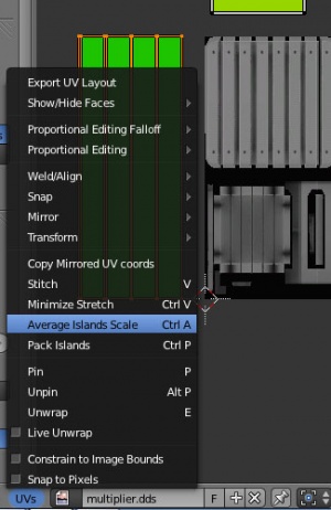
Your UV island should now be all different colors. These colors represent the area relation between the islands. The closer the island's color is to blue in the spectrum, the closer it's size is in relation to other islands. It's okay if that doesn't make sense, in short we want them all to be as close to blue as possible. To do this, (with all the islands selected)go to UV->Average Island Scale. Now they should all be blue and sized correctly.
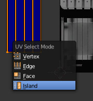
Step 14Now press CTRL+TAB and select Islands from the UV Select mode menu.
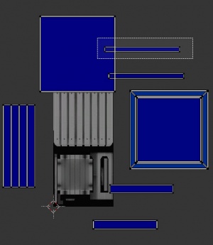
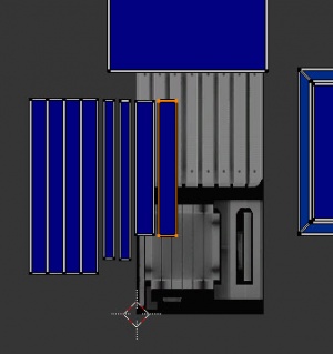
Box select and rotate one set of sides 90 degrees(R then type 90). Press G and move this set next to the legs. Do this with the othe sets of sides.
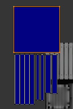
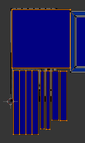
Select the top and move it directly above the legs and sides.
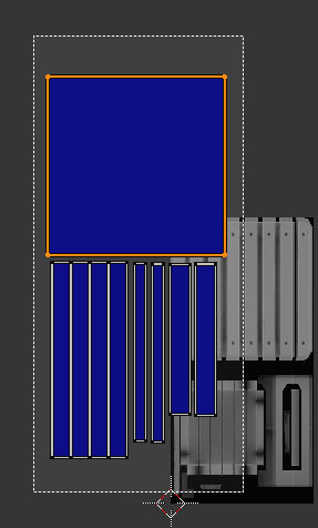
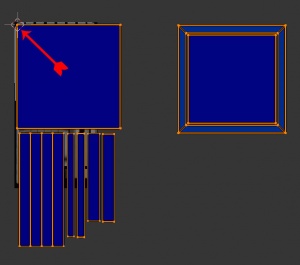
Box select the top, sides, and legs, and move them so that the top left corner of the top island is inside the top left corner of the image.
Step 15Go to Select->Inverse(or press CTRL+I) to select the two bottom islands. Press G and move them away from the other islands.
Left-click the top left corner of the the image. The places the 2D cursor where you clicked. Press the '.' key to change the pivot point to the 2D cursor, and press A until everything is selected.
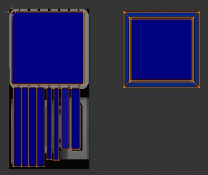
Press S and scale down until the top and legs fit inside the image. We'll leave the bottom parts where they are for now. Go to File->Save to save your .blend file.
In Part 3, we will start baking the textures. Need Help? Got Questions?Please post any comment or questions in this thread |
