Tutorials:Creating An End Table In Blender 2.5 Part 1
| Tutorials by Category | |
|---|---|
|
CAS | Patterns | Objects | Building | Worlds | Modding | Modding Reference |
|
Introduction
This tutorial is part 1 in a series of tutorials which will take you through the process of creating an end table for The Sims 3 in Blender 3D. The series will cover the basics of cloning, meshing, UV mapping, and texturing an object and getting it in the game.
What You Will Need(for the whole series):
- Blender 3D 2.5
- Blender 2.5 TS3 Tools
- DXTBmp
- the latest version of S3OC
- The latest verison of S3PE
- TextureTweaker
This tutorial will be based on the setup described in this tutorial. I strongly advise doing it proceeding.
| cmo says: If it seems like I'm doing something a different way than I stated in a previous step(i.e using a shortcut instead of a menu), it is because I'm trying to show you different ways to do things, so you can see what works best for you. |
Cloning
Step 1
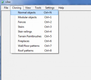
Create a project folder and name it 'end table'. Start s3oc, and click Cloning->Normal Objects, and wait while S3oc loads the game objects.
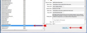
Scroll down through the names until you find 'Table:tableEndDeckAdirondack'. Select it and click 'Clone or Fix...'.
Step 2
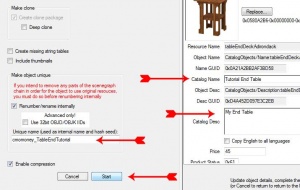
In the Options window, under 'Unique Name' type 'cmomoney_TableEndTutorial' using your username instead of mine. On the left under Overview, change the Catalog name to 'Tutorial End Table', and change the Catalog Desc to "My End Table" then click Start.
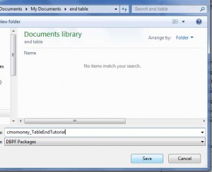
Navivigate to the project folder you created and name the file the same as the Unique Name and click Save. Once s3oc is done saving the file, click OK and close s3oc.
| cmo says: After I clone a package and before I start working on it, I copy the package file(right-click on the file and select copy). This way, if I mess up something, I always have the copy to pull the original resources from. |
Getting The Mesh
Step 3
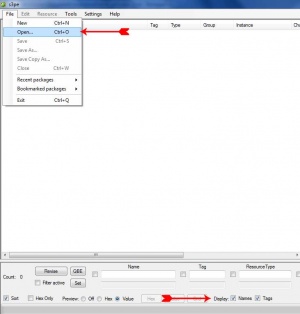
Open s3pe and click File->Open. Navigate to you project folder and open the clone package you created. Make sure that at the bottom of the s3pe window, next to 'Display', that the Names and Tags boxes are checked.
Step 4
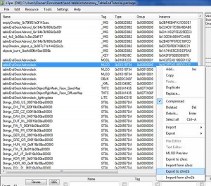
In the window, select the resource with the tag 'MLOD' and the group '0x00000000'. This is the high detail mesh. Right-click on it, and select 'Export to .s3m2b'. Navigate to your project folder and press Save. Close s3pe.
Step 5
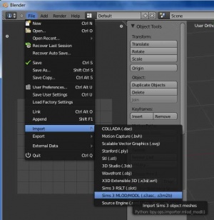
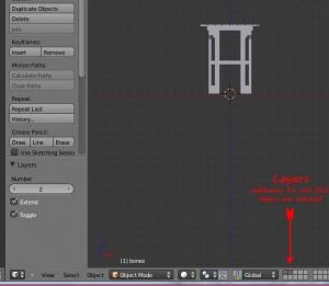
Open Blender, and click File->Import->Sims 3 MLOD/MODL.
Navigate to your project folder and select the 'grp00000000_TableEndDeckAdirondack_filebase.s3m2b'. Then mesh is imported and placed in the 3d view.
clear=all>
Making Your Mesh: The Top
Step 6
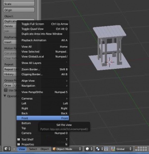
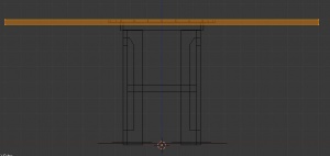
Click View->Front to go to the front view.
While holding SHIFT, press 2. This enables layer 2, where we will be putting our mesh.
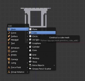
Press SHIFT+A to bring up the Add mesh menu. Select Mesh->Cube to add a cube.
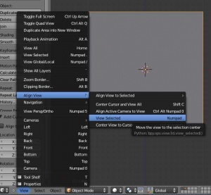
Click View->Align View->Selected to set the view to the cube.
Step 7
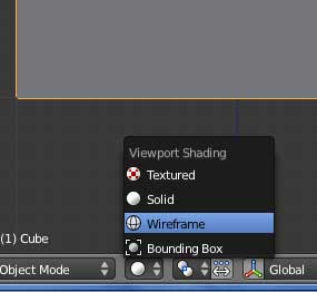
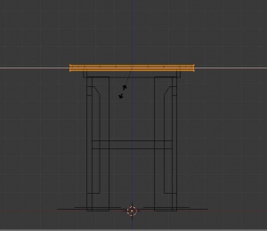
At the bottom of the 3d View, there is a button with a white ball on it. This is the Shading button. Click it and select 'wireframe', so we can see the table through our cube.
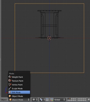
To the left of that button is the current mode. Click it and select Edit mode(or press TAB).
Step 8
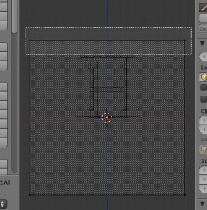
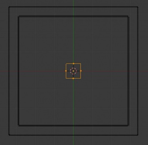
Now we'll use this cube to make out tabletop. Press A to deselect all the vertices(they will be black instead of orange). Press B to enable Box Selection mode, and left-click and drag a box around the top vertices of the cube.
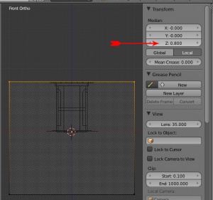
The Properties panel is on the right side of the 3d view, and is toggled with the N key. In the Properties panel under 'Transform', change the Z value to 0.8. This moves the selected vertices to the appropriate table height.
Step 9
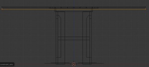
Now press CTRL+I to invert the selection to the bottom vertices. Press G(Grab mode) and press Z to constrain on the Z axis, so the vertices will only move up and down. Move the vertices up until they are a little bit under the original tabletop's bottom surface, and left-click to set them.
| cmo says: If you need more viewing space, you can press CTRL+DOWNARROW to toggle fullscreen for the window your cursor is in. Also scrolling and the NUM+ and NUM- keys zoom in and out. |
Step 10
Press A twice(once to deselect everything, again to select all).
Press S(scale mode) and then press SHIFT+Z(excludes the z axis from scaling). Scale the cube down until the sides match the width of the original table's top. Press A again to deselect everything.
Step 11
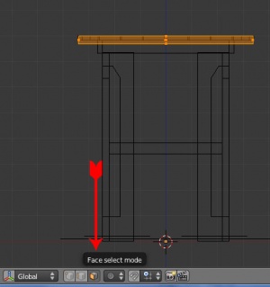
At the bottom of the 3d view again, there are three buttons with cubes in them: one with an orange dot, one with an orange line, and one with an orange square. These are the Mesh Select modes; vertex, edge, and face. Click the face select(the square).
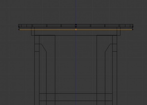
The vertices will disappear, and there will be black dots in the center of each face. You'll see three in the middle of you tabletop, right-click the bottom one to select the bottom face. Press E(extrude) then quickly press ESC(cancel). This creates another face.
Step 12
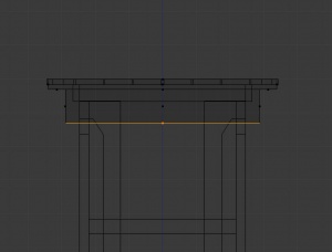
Press S and type 0.85 to to scale the new face down 85% it's size, then press ENTER. Press E again and type 0.1 to move that new face down. We are done modeling the tabletop, so press Go back to Object mode(TAB) and press Z to change the shading to solid. We also don't need to see the original anymore, so press 2 to only see the layer 2.
Step 13
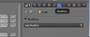
In the Properties Editor on the far right, click the Modifiers button(the wrench).
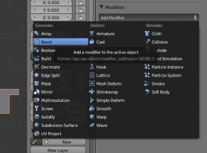
Click Add Modifier, and select Bevel.
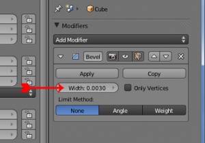
In the Bevel modifier that is added, change the Width to .003. This gives a nice round egde to the tabletop. With your cursor in the 3d view, press the middle mouse button and move around to admire you masterpiece.
Making Your Mesh: The Legs
Step 14
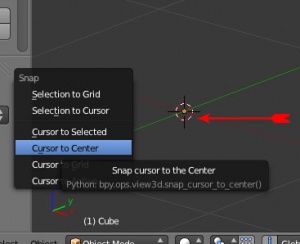
Now for the legs. If for some reason the 3d cursor(the crosshairs with the red and white circle) is not in the in the cennter(where the axis lines meet) press SHIFT+C and select 'Cursor to Center'.
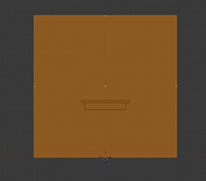
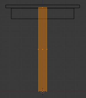
Switch to Front view(View->Front or NUM1), make another cube(SHIFT+A, Mesh->Cube), and go into Edit mode(TAB). Press G(grab), then Z(on Z axis), the type 1 to move the cube up 1 unit, which places the bottom of it on the 'floor'. Change the shading to wireframe(Z).
Step 15
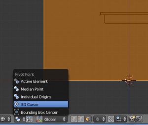
To the right of the Shading mode button(see step 7), there is the Pivot Center button. Click it and select 3D Cursor. Now any scaling/rotating we do will be centered on the 3d cursor's position.
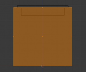
Press S(scale) and scale the cube down until the top meets the bottom side of the top part of the tabletop(the part before we extruded).
Press S again, then SHIFT+Z, then type 0.1.
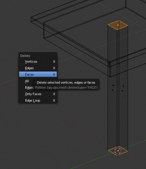
Right-click on the top face then hold SHIFT and right-click(add to selection) the bottom face. Press X and select Faces to delete those faces.
Step 16
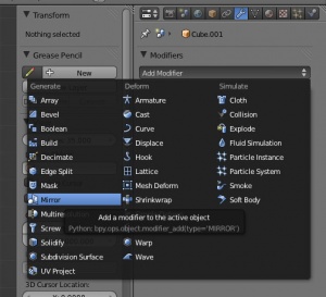
Now add a modifier(step 13), but this time select the Mirror modifier.
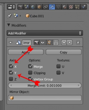
In the modifier under Axis, check the X(should be checked by default) and the Y. I know, you saying "That didn't do anything", but it did.
Press A(select all) and go into top view(View->Top or Num7).
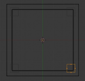
Now press G and move the cube until it is just outside the inner square's bottom-right corner, which is the bottom part of the tabletop(extruded part).
Step 17
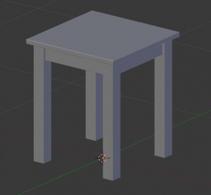
Go back to Object mode, and change the shading to solid. You should now see that your table now has four legs, even though you only meshed one. Cool, huh? Add a Bevel modifier just like the one in step 13 and you are done modelling the table. Go to File->Save and Save the .blend file in your project folder.
In the Part 2, we will work on the UV mapping of the table. Go to Part 2
Need Help? Got Questions?
Please post any comment or questions in this thread
| Tutorials by Category | |
|---|---|
|
CAS | Patterns | Objects | Building | Worlds | Modding | Modding Reference |
