Difference between revisions of "Tutorials:TS3 HTMG SectH1 Cycle1"
From SimsWiki
EllaCharm3d (Talk | contribs) |
EllaCharm3d (Talk | contribs) (→formatted, and images uploaded) |
||
| Line 18: | Line 18: | ||
* Objective here is to place a new table top using the height of the original table as our guide. We will be creating an oval shape, so I have chosen the Cylinder primitive with these settings.<br><br> | * Objective here is to place a new table top using the height of the original table as our guide. We will be creating an oval shape, so I have chosen the Cylinder primitive with these settings.<br><br> | ||
| − | * [[Image:EllaMeshTutorial_100.gif|right]]After you<nowiki>’</nowiki>ve hidden the groups except for top <nowiki><</nowiki>No Material<nowiki>></nowiki>, tab over to '''Model''' and click '''Cylinder'''. Enter the values for '''Stacks''' and '''Slices''' as shown on the right. The stack is analogous to how many levels/floors you want your house to be and Slices is just that – how many pie slices the circle contains. The slices determines how smooth a circle you get.<br><br clear="all"/> | + | * [[Image:EllaMeshTutorial_100.gif|right]]After you<nowiki>’</nowiki>ve hidden the groups except for <tt>top <nowiki><</nowiki>No Material<nowiki>></nowiki></tt>, tab over to '''Model''' and click '''Cylinder'''. Enter the values for '''Stacks''' and '''Slices''' as shown on the right. The stack is analogous to how many levels/floors you want your house to be and Slices is just that – how many pie slices the circle contains. The slices determines how smooth a circle you get.<br><br clear="all"/> |
*[[Image:EllaMeshTutorial_101.gif|right]]The default values are 6 stacks (6 white arrows) and 12 slices (12 of the yellow arrows) and you<nowiki>’</nowiki>ll get this cylinder (I have left out the Front viewport), with both ends capped – i.e. it is a closed cylinder, which you can choose from the dropdown.<br> | *[[Image:EllaMeshTutorial_101.gif|right]]The default values are 6 stacks (6 white arrows) and 12 slices (12 of the yellow arrows) and you<nowiki>’</nowiki>ll get this cylinder (I have left out the Front viewport), with both ends capped – i.e. it is a closed cylinder, which you can choose from the dropdown.<br> | ||
| Line 24: | Line 24: | ||
<br clear="all"/> | <br clear="all"/> | ||
| − | * [[Image:EllaMeshTutorial_01.png|right|350px]]Start at the top-left corner of the Front viewport – Click<nowiki>+</nowiki>Drag until you reach the other end of the table (direction of yellow arrow). Now, we have a circular table top.<br><br clear="all"/> | + | * [[Image:EllaMeshTutorial_01.png|right|350px]]Start at the top-left corner of the Front viewport – <tt>Click<nowiki>+</nowiki>Drag</tt> until you reach the other end of the table (direction of yellow arrow). Now, we have a circular table top.<br><br clear="all"/> |
* [[Image:EllaMeshTutorial_107.png|right|350px]]Let<nowiki>’</nowiki>s hide the rectangular table top.<br><br clear="all"/> | * [[Image:EllaMeshTutorial_107.png|right|350px]]Let<nowiki>’</nowiki>s hide the rectangular table top.<br><br clear="all"/> | ||
* I do not have the greatest eye in gauging distances, shapes and sizes, so I<nowiki>’</nowiki>ll be applying a background image to help me shape the circle to an oval.<br> | * I do not have the greatest eye in gauging distances, shapes and sizes, so I<nowiki>’</nowiki>ll be applying a background image to help me shape the circle to an oval.<br> | ||
| − | ** Right-click at the '''Top''' viewport<br> | + | ** <tt>Right-click</tt> at the '''Top''' viewport<br> |
** Select '''Choose Background Image'''<br> | ** Select '''Choose Background Image'''<br> | ||
** Click the [[Image:EllaMeshTutorial_265.png]] button, navigate to an image you want to use (''I have included this background in the tutorial resources folder so you can follow along'')<br> | ** Click the [[Image:EllaMeshTutorial_265.png]] button, navigate to an image you want to use (''I have included this background in the tutorial resources folder so you can follow along'')<br> | ||
| Line 41: | Line 41: | ||
|} | |} | ||
<br clear="all"/> | <br clear="all"/> | ||
| − | * [[Image:EllaMeshTutorial_113.png|right|350px]] Background appearing under our circle.<br><br clear="all"/> | + | * [[Image:EllaMeshTutorial_113.png|right|350px]] Background appearing under our circle.<br> |
| − | + | ** If the image is too big, you need to resize it.<br clear="all"/> | |
| + | <br><br> | ||
* [[Image:EllaMeshTutorial_112.png|right|350px]]We are going to work on half the circle and then have ms3d mirror it for us. | * [[Image:EllaMeshTutorial_112.png|right|350px]]We are going to work on half the circle and then have ms3d mirror it for us. | ||
| − | ** Select the left half as shown here, making sure you do not include the center line. | + | ** Select the left half as shown here, making sure you do not include the center line. And delete these vertices. |
** Don<nowiki>’</nowiki>t remember how? | ** Don<nowiki>’</nowiki>t remember how? | ||
*** Tab to '''Model''' | *** Tab to '''Model''' | ||
| Line 51: | Line 52: | ||
*** Uncheck '''Ignore''' '''Backfaces''' | *** Uncheck '''Ignore''' '''Backfaces''' | ||
*** Make your selection<br clear="all"/> | *** Make your selection<br clear="all"/> | ||
| − | + | <br><br> | |
* [[Image:EllaMeshTutorial_115.png|right|350px]]After we<nowiki>’</nowiki>ve done our selection, verify that both top and bottom vertices of the circle are selected as indicated by the blue arrows.<br clear="all"/> | * [[Image:EllaMeshTutorial_115.png|right|350px]]After we<nowiki>’</nowiki>ve done our selection, verify that both top and bottom vertices of the circle are selected as indicated by the blue arrows.<br clear="all"/> | ||
| − | + | <br><br> | |
* [[Image:EllaMeshTutorial_116.png|right|350px]]If at any time you selected the wrong set of vertices/faces, | * [[Image:EllaMeshTutorial_116.png|right|350px]]If at any time you selected the wrong set of vertices/faces, | ||
| − | ** firstly press CTRL<nowiki>+</nowiki>Z | + | ** firstly press <tt>CTRL<nowiki>+</nowiki>Z</tt> |
** click anywhere in gray area of viewport to deselect | ** click anywhere in gray area of viewport to deselect | ||
** then check your '''Select''' '''Options''': uncheck or check '''Ignore''' '''Backfaces''' – depending on your objective and whether you wanted Vertices or Faces.<br clear="all"/> | ** then check your '''Select''' '''Options''': uncheck or check '''Ignore''' '''Backfaces''' – depending on your objective and whether you wanted Vertices or Faces.<br clear="all"/> | ||
| − | + | <br><br> | |
* We are left with a semicircle, now. We<nowiki>’</nowiki>ll be moving vertices to fit our oval shape. | * We are left with a semicircle, now. We<nowiki>’</nowiki>ll be moving vertices to fit our oval shape. | ||
| − | : Click on the top vertex lying on the center line. With '''Ignore''' '''Backfaces''' unchecked, we<nowiki>’</nowiki>ll get the top & bottom vertices together, then click [[Image:EllaMeshTutorial_267.png]].<br clear="all"/> | + | : <tt>Click</tt> on the top vertex lying on the center line. With '''Ignore''' '''Backfaces''' unchecked, we<nowiki>’</nowiki>ll get the top & bottom vertices together, then click [[Image:EllaMeshTutorial_267.png]].<br clear="all"/> |
:[[Image:EllaMeshTutorial_117.gif|right]]Since we shall be doing a move manually by dragging, ensure all the axes buttons are selected in the '''Move Options'''.<br clear="all"/> | :[[Image:EllaMeshTutorial_117.gif|right]]Since we shall be doing a move manually by dragging, ensure all the axes buttons are selected in the '''Move Options'''.<br clear="all"/> | ||
| − | :[[Image:EllaMeshTutorial_118.gif|right]]Click<nowiki>+</nowiki>drag the vertex to the center line of our oval outline in the '''y-axis''' direction. You can constraint the '''x-''' and '''z-axes''' movements if your mouse is too sensitive and dragging is difficult – press the buttons so "they pop-up" and turn gray(deselected) instead of blue(selected). | + | :[[Image:EllaMeshTutorial_118.gif|right]]<tt>Click<nowiki>+</nowiki>drag</tt> the vertex to the center line of our oval outline in the '''y-axis''' direction. You can constraint the '''x-''' and '''z-axes''' movements if your mouse is too sensitive and dragging is difficult – press the buttons so "they pop-up" and turn gray(deselected) instead of blue(selected).<br clear="all"/> |
| + | <br> | ||
| + | * [[Image:EllaMeshTutorial_119.png|right|350px]]This is the result.<br clear="all"/> | ||
| + | <br> | ||
| + | * [[Image:EllaMeshTutorial_120.png|right|250px]]We will also start using keyboard shortcuts to speed up. These are the keyboard shortcuts for the '''Model''' tab | ||
| − | * [[Image: | + | :We can activate the buttons from any tab (Group, Material, etc), but we still need to tab over to the '''Model''' tab manually, in order to change the options.<br clear="all"/> |
| + | <br> | ||
| + | * [[Image:EllaMeshTutorial_123.png|right|350px]]Now, let<nowiki>’</nowiki>s work on pairs of vertices from the middle horizontal line and move them in the '''x-axis''' direction. | ||
| + | ** Tab over to '''Model''' tab | ||
| + | ** Press '''F1''' | ||
| + | ** Ensure your '''Select Options''' are on '''Vertex''' and '''Ignore Backfaces''' is unchecked | ||
| + | ** Select the 2 vertices as shown. To select more than one vertex, after we have selected one, press and hold the <tt>SHIFT</tt> key while clicking on the other. Selection can also be made by <tt>Left-click-Dragging</tt> over multiple vertices. To deselect is <tt>SHIFT-Right-click</tt>.<br clear="all"/> | ||
| − | + | :{|cellspacing="2" cellpadding = "6" style="border-style:solid; border-color:black; border-width:1px;" width="75%" align="center" | |
| − | + | | [[Image:EllaMeshTutorial 14.jpg|baseline]] Tip: <br> | |
| − | + | <span style="font-size:12px"> | |
| − | + | * ''More info on selection combinations can be found in the ms3d Help – ToolboxModel. I learned to make an airplane from the Beginner’s Guide Tutorial!''<br> | |
| − | + | * ''If you do not get the same results when using the keyboard shortcuts for the Model tab, you might have another program already using that. Start checking with utilities that register shortcuts for global usage (like camera or video capture utilities).''<br></span> | |
| − | + | ||
| − | + | ||
| − | + | ||
| − | + | ||
| − | + | ||
| − | + | ||
| − | + | ||
| − | + | ||
| − | + | ||
| − | + | ||
| − | + | ||
| − | + | ||
| − | + | ||
| − | + | ||
| − | + | ||
| − | + | ||
| − | + | ||
| − | + | ||
| − | + | ||
| − | {|cellspacing=" | + | |
| − | | Tip:<br> | + | |
| − | More info on selection combinations can be found in the ms3d Help – ToolboxModel. I learned to make an airplane from the Beginner’s Guide Tutorial!<br> | + | |
| − | If you do not get the same results when using the keyboard shortcuts for the Model tab, you might have another program already using that. Start checking with utilities that register shortcuts for global usage (like camera or video capture utilities).<br> | + | |
|} | |} | ||
| + | <br><br> | ||
| + | * [[Image:EllaMeshTutorial_122.png|right|350px]]Move it to the outline as shown. | ||
| + | ** With the vertices selected, press '''F2''' | ||
| + | ** <tt>Click-drag</tt> the vertices over along the '''x-axis''' (yellow line)<br clear="all"/> | ||
| + | <br><br> | ||
| + | * [[Image:EllaMeshTutorial_121.png|right|350px]]The 3D view of the above action. I have also started on a couple of vertices at the top and bottom of the center line (drag along '''y-axis''' – blue line) | ||
| + | <br><br> | ||
| + | * So, go back and forth with '''F1''' and '''F2''' and complete the rest.<br clear="all"/> | ||
| + | <br><br> | ||
| + | * [[Image:EllaMeshTutorial_125.png|right|350px]]When we have finished, we get:<br clear="all"/> | ||
| + | <br><br> | ||
| + | * Let<nowiki>’</nowiki>s mirror this to get the full table top. | ||
| + | ** Tab over to '''Group''' and select this Cylinder. | ||
| + | ** [[Image:EllaMeshTutorial_127.jpg|right|220px]]Choose '''Duplicate Selection''' from the '''Edit''' menu or <tt>CTRL<nowiki>+</nowiki>D</tt><br clear="all"/> | ||
| + | ** [[Image:EllaMeshTutorial_128.png|right|200px]]Then go to '''Vertex''' menu and select '''Mirror Left''' ←→ '''Right'''<br clear="all"/> | ||
| + | ** [[Image:EllaMeshTutorial_129.png|right|350px]]Result shown on next pic.<br clear="all"/> | ||
| + | <br><br> | ||
| + | * Oh noes! We have a gap! We forgot to align the right oval to lie exactly on the '''y-axis''' so the result is our two halves are off center. | ||
| + | <br><br> | ||
| + | * Let<nowiki>’</nowiki>s close this great divide. We can either | ||
| + | ** UNDO the mirror and duplication and align our right oval first, then REDO the mirror and duplication or | ||
| + | ** nudge each half closer together. | ||
| + | <br><br> | ||
| + | * [[Image:EllaMeshTutorial_130.gif|right]]I chose the 2<sup>nd</sup> option as it seems simpler (at the time). | ||
| + | ** Deselect everything by clicking on any gray area | ||
| + | ** Tab over to '''Group''' tab, select the first cylinder (our original right half) | ||
| + | ** Tab over to '''Model''' tab | ||
| + | ** Press '''F2''' to activate the '''Move Options''' | ||
| + | ** Enter the following value above the '''X''' button – we want to nudge the oval to the left, so it is negative for the '''x-axis''' as it is going in the opposite direction of the yellow line. If you want to constraint movement in the '''y-''' and '''z-axes''', deselect those. | ||
| + | ** Then click '''Move''' once. | ||
| + | ** If gap is still there, let<nowiki>’</nowiki>s repeat the same for the left half so we can maintain the center of origin of our mesh. But this time, to nudge the left half to the right, we need to remove the "'''-'''" sign. | ||
| + | ** Repeat as many times as necessary, going back and forth until the gap is closed. | ||
| + | ** Now, we could of course just drag the halves over each other, but I<nowiki>’</nowiki>m clumsy and cannot do delicate work with such precision. And why do manual labor when the computer can do it for us?<br clear="all"/> | ||
| + | <br><br> | ||
| + | * Now, when we<nowiki>’</nowiki>re done closing the gap, | ||
| + | ** [[Image:EllaMeshTutorial_131.png|right|350px]]select middle vertices so we can join them up<br clear="all"/> | ||
| + | ** [[Image:EllaMeshTutorial_133.png|right|250px]]then navigate to '''Vertex''' menu and click on '''Weld Together'''<br clear="all"/> | ||
| + | <br><br> | ||
| + | * OK, let<nowiki>’</nowiki>s bring back our table groups and see where we are. | ||
| + | ** select each group in turn from the '''Group''' tab | ||
| + | ** [[Image:EllaMeshTutorial_134.png|right|350px]]my next picture shows the oval top is way too big, we need to scale it down.<br clear="all"/> | ||
| + | <br><br> | ||
| + | * Resizing the oval top smaller. | ||
| + | ** Press '''F4''', | ||
| + | ** in the '''Scale''' '''Options''', enter those values in red box | ||
| + | ** press [[Image:EllaMeshTutorial_268.png]] | ||
| + | ** [[Image:EllaMeshTutorial_135.png|right|350px]]I get the following, it is still too big for my liking, so I UNDO<br clear="all"/> | ||
| + | ** [[Image:EllaMeshTutorial_137.png|right|350px]]I tried the values in the next pic, and that looks fine, although it gets swallowed in by the rectangular table top.<br clear="all"/> | ||
| + | <br><br> | ||
| + | * For the next bits, I will speed through and tell you why I decide to put this mesh aside for now, until I get more meshing experience. | ||
| + | ** I proceeded to delete the rectangle top and make the legs and then the shadows | ||
| + | ** went so far as to loading the exported .obj map into LithUnwrap – then I hit a wall | ||
| + | ** I didn<nowiki>’</nowiki>t know how to UV-map it to the way I envisioned because the legs are slanted and I had missing faces on some vertices (the black legs) or unsmoothed or not normal or whatever | ||
| + | ** so, back to the drawing board. | ||
| − | [[Image: | + | [[Image:EllaMeshTutorial_139.png|center|640px]] |
| − | + | ||
| − | + | ||
| − | + | ||
| − | + | ||
| − | + | ||
| − | + | ||
| − | + | ||
| − | + | ||
| − | + | ||
| − | + | ||
| − | + | ||
| − | + | ||
| − | + | ||
| − | + | ||
| − | + | ||
| − | + | ||
| − | + | ||
| − | + | ||
| − | + | ||
| − | + | ||
| − | + | ||
| − | + | ||
| − | + | ||
| − | + | ||
| − | + | ||
| − | + | ||
| − | + | ||
| − | + | ||
| − | + | ||
| − | + | ||
| − | + | ||
| − | + | ||
| − | + | ||
| − | + | ||
| − | + | ||
| − | + | ||
| − | + | ||
| − | + | ||
| − | + | ||
| − | + | ||
| − | + | ||
| − | + | ||
| − | + | ||
| − | + | ||
| − | + | ||
| − | + | ||
| − | + | ||
| − | + | ||
| − | + | ||
| − | + | ||
| − | + | ||
| − | + | ||
| − | + | ||
| − | + | ||
| − | + | ||
| − | + | ||
| − | + | ||
| − | + | ||
| − | + | ||
| − | + | ||
| − | + | ||
| − | + | ||
| − | + | ||
| − | + | ||
| − | + | ||
| − | + | ||
| − | + | ||
| − | + | ||
| − | + | ||
| − | + | ||
| − | + | ||
| − | + | ||
| − | + | ||
| − | + | ||
| − | + | ||
| − | + | ||
| − | + | ||
| − | + | ||
| − | + | ||
| − | + | ||
| − | + | ||
| − | + | ||
| − | + | ||
| − | + | ||
| − | + | ||
| − | + | ||
| − | + | ||
| − | + | ||
| − | + | ||
| − | + | ||
| − | + | ||
| − | + | ||
| − | + | ||
| − | + | ||
| − | + | ||
| − | + | ||
| − | + | ||
| − | + | ||
| − | + | ||
| − | + | ||
| − | + | ||
| − | + | ||
| − | + | ||
| − | + | ||
| − | + | ||
| − | + | ||
| − | + | ||
| − | + | ||
| − | + | ||
| − | + | ||
| − | + | ||
| − | + | ||
| − | + | ||
| − | + | ||
| − | + | ||
| − | |||
Revision as of 17:47, 24 April 2010
| Meshing in Milkshape | |
|---|---|
H. Meshing in Milkshape
H6. Cycle 1
- OK, picking up from where we left off, (before I started to tell a story, there), at this point you should have some extra groups added to the original 2. Before we proceed any further, if you’re following along, save our imported mesh as an .ms3d file so the grouping information will not be lost.
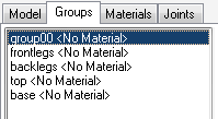

- You should have at the minimum, these 5 (albeit with different names). Go ahead and hide all groups except for the table-top group.
- Objective here is to place a new table top using the height of the original table as our guide. We will be creating an oval shape, so I have chosen the Cylinder primitive with these settings.
- After you’ve hidden the groups except for top <No Material>, tab over to Model and click Cylinder. Enter the values for Stacks and Slices as shown on the right. The stack is analogous to how many levels/floors you want your house to be and Slices is just that – how many pie slices the circle contains. The slices determines how smooth a circle you get.

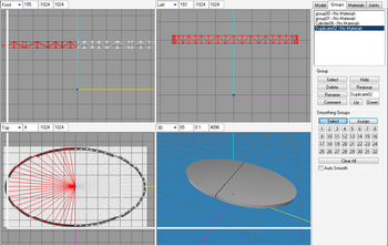
- The default values are 6 stacks (6 white arrows) and 12 slices (12 of the yellow arrows) and you’ll get this cylinder (I have left out the Front viewport), with both ends capped – i.e. it is a closed cylinder, which you can choose from the dropdown.


- Start at the top-left corner of the Front viewport – Click+Drag until you reach the other end of the table (direction of yellow arrow). Now, we have a circular table top.


- Let’s hide the rectangular table top.


- I do not have the greatest eye in gauging distances, shapes and sizes, so I’ll be applying a background image to help me shape the circle to an oval.
- Right-click at the Top viewport
- Select Choose Background Image
- Click the
 button, navigate to an image you want to use (I have included this background in the tutorial resources folder so you can follow along)
- Set the scale of the image, if it is too big or small, adjust it as necessary (depends on your screen size and resolution)
- Click

- Right-click at the Top viewport


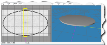
- Background appearing under our circle.

- If the image is too big, you need to resize it.
- If the image is too big, you need to resize it.

- We are going to work on half the circle and then have ms3d mirror it for us.

- Select the left half as shown here, making sure you do not include the center line. And delete these vertices.
- Don’t remember how?
- Tab to Model
- Click Select
- Either Vertex or Face selection mode works
- Uncheck Ignore Backfaces
- Make your selection

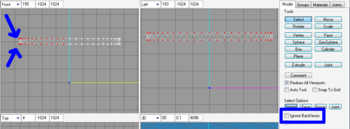
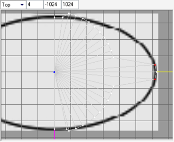
- After we’ve done our selection, verify that both top and bottom vertices of the circle are selected as indicated by the blue arrows.

- If at any time you selected the wrong set of vertices/faces,

- firstly press CTRL+Z
- click anywhere in gray area of viewport to deselect
- then check your Select Options: uncheck or check Ignore Backfaces – depending on your objective and whether you wanted Vertices or Faces.

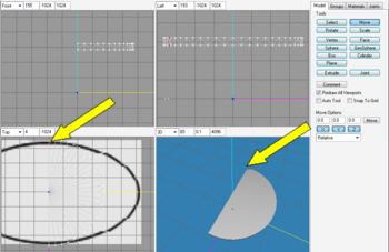
- We are left with a semicircle, now. We’ll be moving vertices to fit our oval shape.
- Click on the top vertex lying on the center line. With Ignore Backfaces unchecked, we’ll get the top & bottom vertices together, then click
 .
.
- Since we shall be doing a move manually by dragging, ensure all the axes buttons are selected in the Move Options.


- Click+drag the vertex to the center line of our oval outline in the y-axis direction. You can constraint the x- and z-axes movements if your mouse is too sensitive and dragging is difficult – press the buttons so "they pop-up" and turn gray(deselected) instead of blue(selected).

- This is the result.

- We will also start using keyboard shortcuts to speed up. These are the keyboard shortcuts for the Model tab


- We can activate the buttons from any tab (Group, Material, etc), but we still need to tab over to the Model tab manually, in order to change the options.
- Now, let’s work on pairs of vertices from the middle horizontal line and move them in the x-axis direction.

- Tab over to Model tab
- Press F1
- Ensure your Select Options are on Vertex and Ignore Backfaces is unchecked
- Select the 2 vertices as shown. To select more than one vertex, after we have selected one, press and hold the SHIFT key while clicking on the other. Selection can also be made by Left-click-Dragging over multiple vertices. To deselect is SHIFT-Right-click.

 Tip:
Tip:
- More info on selection combinations can be found in the ms3d Help – ToolboxModel. I learned to make an airplane from the Beginner’s Guide Tutorial!
- If you do not get the same results when using the keyboard shortcuts for the Model tab, you might have another program already using that. Start checking with utilities that register shortcuts for global usage (like camera or video capture utilities).
- More info on selection combinations can be found in the ms3d Help – ToolboxModel. I learned to make an airplane from the Beginner’s Guide Tutorial!
- Move it to the outline as shown.
- With the vertices selected, press F2
- Click-drag the vertices over along the x-axis (yellow line)

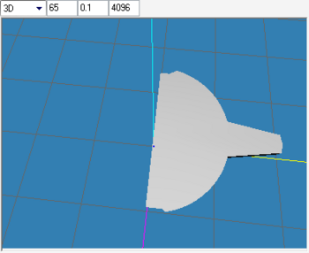
- The 3D view of the above action. I have also started on a couple of vertices at the top and bottom of the center line (drag along y-axis – blue line)

- So, go back and forth with F1 and F2 and complete the rest.
- When we have finished, we get:


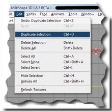
- Let’s mirror this to get the full table top.
- Tab over to Group and select this Cylinder.
- Choose Duplicate Selection from the Edit menu or CTRL+D
- Then go to Vertex menu and select Mirror Left ←→ Right

- Result shown on next pic.


- Oh noes! We have a gap! We forgot to align the right oval to lie exactly on the y-axis so the result is our two halves are off center.
- Let’s close this great divide. We can either
- UNDO the mirror and duplication and align our right oval first, then REDO the mirror and duplication or
- nudge each half closer together.
- I chose the 2nd option as it seems simpler (at the time).

- Deselect everything by clicking on any gray area
- Tab over to Group tab, select the first cylinder (our original right half)
- Tab over to Model tab
- Press F2 to activate the Move Options
- Enter the following value above the X button – we want to nudge the oval to the left, so it is negative for the x-axis as it is going in the opposite direction of the yellow line. If you want to constraint movement in the y- and z-axes, deselect those.
- Then click Move once.
- If gap is still there, let’s repeat the same for the left half so we can maintain the center of origin of our mesh. But this time, to nudge the left half to the right, we need to remove the "-" sign.
- Repeat as many times as necessary, going back and forth until the gap is closed.
- Now, we could of course just drag the halves over each other, but I’m clumsy and cannot do delicate work with such precision. And why do manual labor when the computer can do it for us?

- Now, when we’re done closing the gap,
- select middle vertices so we can join them up
- then navigate to Vertex menu and click on Weld Together

-


- OK, let’s bring back our table groups and see where we are.
- select each group in turn from the Group tab
- my next picture shows the oval top is way too big, we need to scale it down.

- Resizing the oval top smaller.
- Press F4,
- in the Scale Options, enter those values in red box
- press

- I get the following, it is still too big for my liking, so I UNDO

- I tried the values in the next pic, and that looks fine, although it gets swallowed in by the rectangular table top.


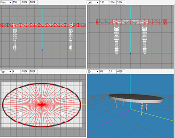
- For the next bits, I will speed through and tell you why I decide to put this mesh aside for now, until I get more meshing experience.
- I proceeded to delete the rectangle top and make the legs and then the shadows
- went so far as to loading the exported .obj map into LithUnwrap – then I hit a wall
- I didn’t know how to UV-map it to the way I envisioned because the legs are slanted and I had missing faces on some vertices (the black legs) or unsmoothed or not normal or whatever
- so, back to the drawing board.

| |
|
TS3 HTMG SectH1 Cycle1 | |
|