Difference between revisions of "Tutorials:TS3 HTMG SectH2 Cycle2"
From SimsWiki
EllaCharm3d (Talk | contribs) |
EllaCharm3d (Talk | contribs) (→formatted, with images) |
||
| Line 13: | Line 13: | ||
H7. '''Cycle 2''' | H7. '''Cycle 2''' | ||
| − | + | * Things to note:<br> | |
| − | + | ** '''Bones & Joints'''<br> | |
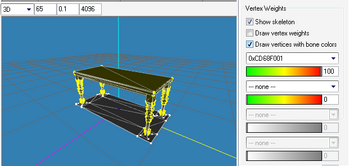
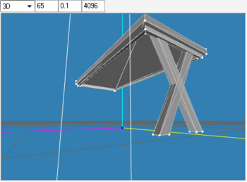
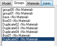
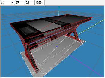
| − | '''Bones & Joints''' | + | ***[[Image:EllaMeshTutorial_145.png|right|350px]]I see a lot of posts in the forum about the bone assignment error message check Wes had put in his Export plug-in, and what to do about it. It is easy to click the button and ignore it, but it can become a bad habit when the time comes when the joint is necessary to the mesh – like when we graduate to animation – so, another point to note during analysis is the Joints tab. This is a freshly imported mesh of our same table with the following options in the Vertex Weights options. This shows that the one joint (0xCD68F001) that this mesh has is assigned to "group01" – our main mesh, so we have to do the same when we regroup and export our mlod 00000 mesh later on.<br><br><br clear="all"/> |
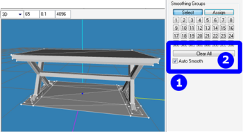
| − | + | **'''Black mesh with AutoSmooth On'''. | |
| − | [[Image:EllaMeshTutorial_145.png| | + | *** This would mess up how it looks in-game. To correct, '''Select All''', and check the '''Auto Smooth''' in the '''Smoothing Groups''' options in the '''Groups''' tab, then click the '''Clear All''' button. Then uncheck the '''Auto Smooth''' again to turn it off. <br> |
| − | + | *** [[Image:EllaMeshTutorial_144.png|right|350px|Before]]Before picture and <br clear="all"/> | |
| − | I see a lot of posts in the forum about the bone assignment error message check Wes had put in his Export plug-in, and what to do about it. It is easy to click the button and ignore it, but it can become a bad habit when the time comes when the joint is necessary to the mesh – like when we graduate to animation – so, another point to note during analysis is the Joints tab. This is a freshly imported mesh of our same table with the following options in the Vertex Weights options. This shows that the one joint (0xCD68F001) that this mesh has is assigned to "group01" – our main mesh, so we have to do the same when we regroup and export our mlod 00000 mesh later on. | + | *** [[Image:EllaMeshTutorial_143.png|right|350px|After]]After picture.<br><br><br clear="all"/> |
| − | + | * For the next mesh, I<nowiki>’</nowiki>ve wised up and only used Box primitives that I know how to UVmap and duplicate and mirror using '''Front''' ←→ '''Back''' and '''Left''' ←→ '''Right'''. I did not create simple boxes for legs and table top because there wouldn<nowiki>’</nowiki>t be any vertices and faces to reduce for our low-poly versions.<br><br> | |
| − | '''Black mesh with AutoSmooth On'''. | + | * Reminder: |
| − | + | ** Keyboard shortcuts: '''F1-Select''', '''F2-Move''', '''F4-Scale'''<br> | |
| − | + | ** if I use the [[Image:EllaMeshTutorial_269.png]] button, it mostly means to do the selection in the '''Groups''' tab versus '''Select''' – means to press '''F1''' in the '''Model''' tab or click-drag the indicated vertex/face<br> | |
| − | + | ** Pan and zoom shortcuts in viewport: | |
| − | + | ::{|border="0" cellspacing="2" width="30%" align="left" | |
| − | + | |⇒ <tt>CTRL<nowiki>+</nowiki>Left-click-drag</tt> | |
| − | This would mess up how it looks in-game. To correct, '''Select All''', and check the '''Auto Smooth''' in the '''Smoothing Groups''' options in the '''Groups''' tab, then click the '''Clear All''' button. Then uncheck the '''Auto Smooth''' again to turn it off. Before | + | | pan viewport |
| − | + | ||
| − | + | ||
| − | + | ||
| − | + | ||
| − | + | ||
| − | * Keyboard shortcuts: '''F1-Select''', '''F2-Move''', '''F4-Scale''' | + | |
| − | * Pan and zoom shortcuts in viewport: | + | |
| − | + | ||
| − | {|border="0" cellspacing="2" width=" | + | |
| − | | | + | |
| − | + | ||
| − | | | + | |
| − | + | ||
|- | |- | ||
| − | | | + | |⇒ <tt>SHIFT<nowiki>+</nowiki>Left-click-drag</tt> |
| − | + | | controlled zoom | |
| − | |controlled zoom | + | |
|- | |- | ||
| − | | | + | |⇒ <tt>SHIFT<nowiki>+</nowiki>mouse-wheel</tt> |
| − | + | | faster zoom | |
| − | | | + | |
| − | + | ||
| − | + | ||
|} | |} | ||
| − | + | <br><br clear="all"/><br> | |
| − | * | + | * Creating the new top |
| − | + | ** If you have followed along from '''Cycle 1''' and regrouped all the groups, hide all groups except for the table "top". | |
| − | + | ** [[Image:EllaMeshTutorial_146.gif|right]]Press '''F1''' and in the '''Select Options''', verify we have the following settings.<br clear="all"/> | |
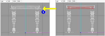
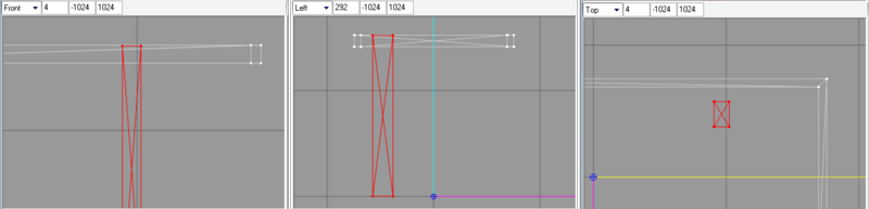
| − | + | ** [[Image:EllaMeshTutorial_147.png|right|350px]]If have not done the regrouping, let<nowiki>’</nowiki>s do it now. Click-Drag the mouse over the lower vertices and ONLY these vertices of the table<nowiki>’</nowiki>s base as shown. We shall regroup this to retain for our mesh, the rest (except for the shadow – "group00") will be deleted.<br clear="all"/> | |
| − | + | <br><br> | |
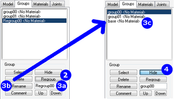
| − | + | * [[Image:EllaMeshTutorial_148.png|right|350px]]Regroup, Rename and Hide | |
| − | + | *# When you did the selection as above and | |
| − | + | *# then click '''Regroup''' – you<nowiki>’</nowiki>ll get a new group in the '''Groups''' list | |
| − | * If you have followed along from '''Cycle 1''' and regrouped all the groups, hide all groups except for the table "top". | + | *# highlight the default name and |
| − | + | *#* enter "<tt>base</tt>" | |
| − | [[Image:EllaMeshTutorial_146.gif| | + | *#* click '''Rename''' |
| − | + | *# click '''Hide''' | |
| − | + | ** '''Save''' first as an ms3d file before we proceed (do it often)<br clear="all"/> | |
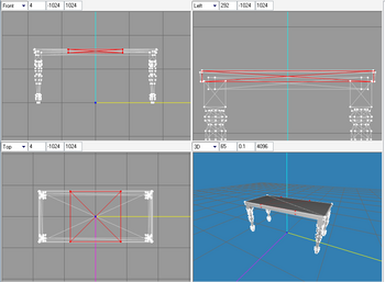
| − | + | ** Use the '''Box''' primitive to create a rectangle in place of the pre-existing table "<tt>top</tt>" | |
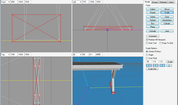
| − | * | + | ** [[Image:EllaMeshTutorial_149.png|right|350px]]Again, use the original rectangular top to gauge table height from center of origin (where the 3 axes meet)<br clear="all"/> |
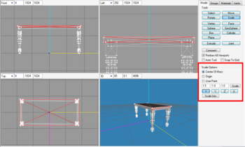
| − | [[Image:EllaMeshTutorial_147.png| | + | ** [[Image:EllaMeshTutorial_150.png|right|350px]]'''Scale''' it, the result below was from using the values in the '''Scale Options''', with '''y-''' & '''z-axes''' constrained; yours would depend on the box size that you drew<br clear="all"/> |
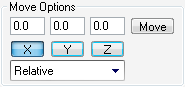
| − | + | ** [[Image:EllaMeshTutorial_152.png||right]]'''Move''' it, if necessary, deselect the other axes to constrain them – it helps – and you can drag in the direction of one axis.<br clear="all"/> | |
| − | If have not done the regrouping, let<nowiki>’</nowiki>s do it now. Click-Drag the mouse over the lower vertices and ONLY these vertices of the table<nowiki>’</nowiki>s base as shown. We shall regroup this to retain for our mesh, the rest (except for the shadow – "group00") will be deleted. | + | <br> |
| − | + | * Making slanted legs to form an X. | |
| − | * Regroup, Rename and Hide | + | ** In '''Groups''' tab, [[Image:EllaMeshTutorial_269.png]] "<tt>group01</tt>" |
| − | * When you did the selection as above and then click '''Regroup''' – you<nowiki>’</nowiki>ll get a new group in the '''Groups''' list | + | ** '''Hide''' "group01" and the top we just made – "<tt>Box03</tt>" for me. |
| − | * highlight the default name and enter "base" | + | ** un-'''Hide''' the box we created before and renamed "<tt>base</tt>". |
| − | * click '''Rename''' | + | ** In the '''Model''' tab, click '''Box''' or <tt>Shift<nowiki>+</nowiki>F3</tt>. Draw out a box in the '''Left''' viewport in the position shown. |
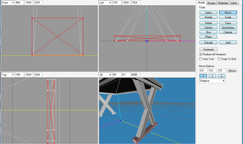
| − | * click '''Hide''' | + | ** Then, '''Scale''' it and '''Move''' it so that it is flush against the base of the table (see '''3D''' view of next pics) [[Image:EllaMeshTutorial_156.png|center|800px]]<br clear="all"/> |
| − | * | + | ** [[Image:EllaMeshTutorial_157.png|right]][[Image:EllaMeshTutorial_269.png]] and '''Duplicate''' this leg, then mirror it '''Front''' ←→ '''Back'''.<br clear="all"/> |
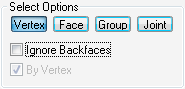
| − | + | ** We are going to cross the legs over to make the X. Press '''F1''' in '''Model''' tab, check your '''Select Options''' matches mine as shown | |
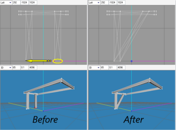
| − | + | ** [[Image:EllaMeshTutorial_158.png|right|350px]]'''Select''' the lower vertices of one leg, like so (''Before'' pic) and then drag it over to meet the vertices of the other leg (in '''z-axis''' direction, constrain others) – see ''After'' pic.<br clear="all"/> | |
| − | '''Save''' first as an ms3d file before we proceed (do it often) | + | ** [[Image:EllaMeshTutorial_269.png]], '''Duplicate''' and '''Mirror''' the slanted box ('''Front''' ←→ '''Back'''). |
| − | + | ** [[Image:EllaMeshTutorial_162.png|right|350px]]So, now, we have an X for legs.<br clear="all"/> | |
| − | + | ** [[Image:EllaMeshTutorial_163.png|right]]Checkpoint: my '''Groups''' list at this point.<br clear="all"/> | |
| − | + | ** [[Image:EllaMeshTutorial_269.png]] and [[Image:EllaMeshTutorial_304.png]] the straight leg (mine was <tt>Box04</tt>), we don<nowiki>’</nowiki>t need it anymore.<br clear="all"/> | |
| − | * Use the '''Box''' primitive to create a rectangle in place of the pre-existing table "top" | + | ** [[Image:EllaMeshTutorial_269.png]] the boxes that form the X ("<tt>Duplicate02</tt>" & "<tt>Duplicate03</tt>" on my list), '''Duplicate''' and '''Mirror''' '''Left''' ←→ '''Right'''; resulting in a new group "<tt>Duplicate04</tt>" (pic shown in next checkpoint)<br clear="all"/> |
| − | * | + | <br><br> |
| − | [[Image:EllaMeshTutorial_149.png| | + | {|cellspacing="2" cellpadding = "6" style="border-style:solid; border-color:black; border-width:1px;" width="80%" align="center" |
| − | + | | [[Image:EllaMeshTutorial 14.jpg|baseline]] Tip: <br> | |
| − | Again, use the original rectangular top to gauge table height from center of origin (where the 3 axes meet) | + | [[Image:EllaMeshTutorial_153.png|right]]<span style="font-size:12px">''If you get a model that is off screen or too small / too big, <tt>right-click</tt> on the viewport and choose one of these options, depending if you want to view all of it or just the selection to bring it up close so we can work on it'' </span> |
| − | + | |} | |
| − | * | + | <br><br> |
| − | + | * Making a wedge for the feet of our table legs. | |
| − | + | ** OK, create another box at the foot of our x-frame legs. | |
| − | [[Image:EllaMeshTutorial_150.png| | + | ** Draw as such, scale (approx .025 in my case) and '''Move''' it in position to the right side |
| − | + | ** [[Image:EllaMeshTutorial_276.png|right|350px]]This pic shows mine has been scaled down and moved to the right-side-legs, but not yet positioned precisely.<br clear="all"/> | |
| − | '''Scale''' it, the result below was from using the values in the '''Scale Options''', with '''y-''' & '''z-axes''' constrained; yours would depend on the box size that you drew | + | ** [[Image:EllaMeshTutorial_277.png|right|350px]]This one has been positioned (see the '''Front''' viewport) – ready for the manipulation to make it into a wedge shape. You might want to raise it slightly off the floor too ('''y-axis''' direction) |
| − | + | ** '''Move''' vertices to make a wedge – I moved the lower outward and the upper inward along the z-axis (pink line) using the following measurements.<br> | |
| − | * | + | ** [[Image:EllaMeshTutorial_164.png|right|350px]]Select the pair of vertices at a bottom corner.<br clear="all"/> |
| − | [[Image:EllaMeshTutorial_152.png| | + | ** Then with a combination of values that fit your model, use the '''Move Options''' to move the vertices ''away'' from the center line. Choose the same values and combination of number of clicks to the other pair, so the other side is equi-distant. This is the reason I don<nowiki>’</nowiki>t use click-drag, I can never be precise enough. [[Image:EllaMeshTutorial_165.gif|center]] |
| − | + | ** To do the other side, deselect, select other pair of vertices and move the same amount with a negative value in options | |
| − | '''Move''' it, if necessary, deselect the other axes to constrain them – it helps – and you can drag in the direction of one axis. | + | ** [[Image:EllaMeshTutorial_166.png|right|350px]]At the end of the above step, my model looks like this. These next pics also show that I have moved the top left corner vertex to meet the leg. |
| − | + | *** '''Move''' the upper vertices in increments of .01 (I think it took four times to make the vertices touch the leg like so). | |
| − | + | ** So, one last vertex left to do.<br clear="all"/> | |
| − | + | ** [[Image:EllaMeshTutorial_168.png|right|350px]]When you<nowiki>’</nowiki>re satisfied with how the wedge looks [[Image:EllaMeshTutorial_269.png]] it (in '''Groups''' tab), '''Duplicate''' and '''Mirror Left''' ←→ '''Right'''. Result of this step<br clear="all"/> | |
| − | + | ** [[Image:EllaMeshTutorial_169.png|right]]Checkpoint: '''Groups''' list after making the wedges.<br clear="all"/><br> | |
| − | + | * Adding a beam to the legs | |
| − | * In '''Groups''' tab, | + | ** [[Image:EllaMeshTutorial_170.png|right|350px]]Add another box at the midpoint of the legs where the Xs meet. Mine came out to be this size. So, same drill – '''Scale''' and '''Move'''.<br clear="all"/> |
| − | [[Image: | + | ** It is still not precisely where I want it – at the middle ('''Front''' viewport) and center ('''Right''' viewport) of the X. |
| − | "group01" | + | ** [[Image:EllaMeshTutorial_171.png|right|350px]]With the beam selected, right-click on the '''Right/Left''' viewport and '''Frame Selection''' and zoom in tight (<tt>SHIFT<nowiki>+</nowiki>Left-click-drag</tt>) as shown here<br clear="all"/> |
| − | * '''Hide''' "group01" and the top we just made – "Box03" for me. | + | ** [[Image:EllaMeshTutorial_172.png|right|350px]] Move using the '''Move Options'''<br clear="all"/> |
| − | * un-'''Hide''' the box we created before and renamed "base". | + | ** [[Image:EllaMeshTutorial_173.png|right|350px]]Checkpoint: '''Groups''' list after making the beam.<br> |
| − | * In the '''Model''' tab, click '''Box''' or Shift<nowiki>+</nowiki>F3. Draw out a box in the '''Left''' viewport in the position shown. | + | ** '''Rename''' them – [[Image:EllaMeshTutorial_269.png]] each group to confirm what it is and [[Image:EllaMeshTutorial_269.png]] other groups as necessary. The before and after pics of renaming my groups.<br clear="all"/> |
| − | * | + | ** [[Image:EllaMeshTutorial_281.png|right|350px]]Let<nowiki>’</nowiki>s bring everything back on screen, from the '''Edit''' menu → '''Select None''' → '''Unhide All''' |
| − | + | ** [[Image:EllaMeshTutorial_269.png]] "group01" and [[Image:EllaMeshTutorial_304.png]]<br clear="all"/> | |
| − | + | ** [[Image:EllaMeshTutorial_38.png|right]]If you right-click in 3D view and select Colored Groups, each group will have its own color. <br clear="all"/> | |
| − | + | **[[Image:EllaMeshTutorial_176.png|right|350px]]Very useful to verify if we had Regrouped correctly<br><br><br clear="all"/> | |
| − | + | * The groundshadow<nowiki>’</nowiki>s size looks fine unadjusted so we shall leave that be. If you want, delete each side<nowiki>’</nowiki>s one square shadow-legs and scale the other to rectangles to match our table<nowiki>’</nowiki>s wedged "feet" shape and size.<br><br> | |
| − | + | * Assigning texture to our groups (if you forget how, instructions are [[Tutorials:TS3_HTMG_ChapH_MeshingMilkshape#assign_mat|here]]) | |
| − | + | ** [[Image:EllaMeshTutorial_177.png|right|350px]]'''Assign''' the main texture jpg that we created previously as a material to all groups except "group00"<br> | |
| − | Then, '''Scale''' it and '''Move''' it so that it is flush against the base of the table (see '''3D''' view of next pics) | + | ** '''Assign''' the dropshadow jpg to "group00" (we can also assign the material in LithUnwrap, but the procedure is more complicated) |
| − | + | ** Our model then, looks like this:<br><br><br clear="all"/> | |
| − | [[Image: | + | * Congratulations! We have completed our first mesh!<br><br> |
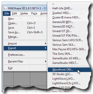
| − | + | * [[Image:EllaMeshTutorial_178.png|right|300px]]Export as a file to UV-map | |
| − | * | + | ** '''Save''' first as an ms3d file |
| − | [[Image:EllaMeshTutorial_157.png| | + | ** select '''Wavefront Obj''' from the '''Export''' menu |
| − | + | ** provide a suitable name and | |
| − | [[Image: | + | ** I<nowiki>’</nowiki>ll see you in the next section. |
| − | and '''Duplicate''' this leg, then mirror it '''Front''' | + | |
| − | * We are going to cross the legs over to make the X. Press '''F1''' in '''Model''' tab, check your '''Select Options''' matches mine as shown | + | |
| − | * | + | |
| − | + | ||
| − | + | ||
| − | [[Image:EllaMeshTutorial_158.png| | + | |
| − | + | ||
| − | '''Select''' the lower vertices of one leg, like so ( | + | |
| − | + | ||
| − | + | ||
| − | + | ||
| − | + | ||
| − | + | ||
| − | + | ||
| − | + | ||
| − | * | + | |
| − | [[Image: | + | |
| − | + | ||
| − | + | ||
| − | , '''Duplicate''' and '''Mirror''' the slanted box ('''Front''' | + | |
| − | * So, now, we have an X for legs. | + | |
| − | + | ||
| − | [[Image:EllaMeshTutorial_163.png| | + | |
| − | + | ||
| − | + | ||
| − | * | + | |
| − | [[Image: | + | |
| − | and | + | |
| − | [[Image: | + | |
| − | the straight leg (mine was Box04), we don<nowiki>’</nowiki>t need it anymore. | + | |
| − | * | + | |
| − | [[Image: | + | |
| − | the boxes that form the X ("Duplicate02" & "Duplicate03" on my list), '''Duplicate''' and '''Mirror''' '''Left''' | + | |
| − | + | ||
| − | 6. Making a wedge for the feet of our table legs. | + | |
| − | + | ||
| − | * OK, create another box at the foot of our x-frame legs. | + | |
| − | * Draw as such, scale (approx .025 in my case) and '''Move''' it in position to the right side | + | |
| − | * This pic | + | |
| − | + | ||
| − | [[Image: | + | |
| − | + | ||
| − | + | ||
| − | + | ||
| − | + | ||
| − | + | ||
| − | + | ||
| − | + | ||
| − | * '''Move''' vertices to make a wedge – I moved the lower outward and the upper inward along the z-axis (pink line) using the following measurements. | + | |
| − | * | + | |
| − | [[Image:EllaMeshTutorial_164.png| | + | |
| − | + | ||
| − | Select the pair of vertices at a bottom corner. | + | |
| − | * Then with a combination of values that fit your model, use the '''Move Options''' to move the vertices ''away'' from the center line. Choose the same values and combination of number of clicks to the other pair, so the other side is equi-distant. This is the reason I don<nowiki>’</nowiki>t use click-drag, I can never be precise enough. | + | |
| − | + | ||
| − | [[Image: | + | |
| − | + | ||
| − | + | ||
| − | + | ||
| − | * To do the other side, deselect, select other pair of vertices and move the same amount with a negative value in options | + | |
| − | * At the end of the above step, my model looks like this. These next pics also show that I have moved the top left corner vertex to meet the leg. | + | |
| − | * '''Move''' the upper vertices in increments of .01 (I think it took four times to make the vertices touch the leg like so). | + | |
| − | * | + | |
| − | + | ||
| − | + | ||
| − | So, one last vertex left to do. | + | |
| − | + | ||
| − | [[Image:EllaMeshTutorial_168.png| | + | |
| − | + | ||
| − | + | ||
| − | + | ||
| − | + | ||
| − | [[Image: | + | |
| − | it (in '''Groups''' tab), '''Duplicate''' and '''Mirror Left''' | + | |
| − | + | ||
| − | [[Image:EllaMeshTutorial_169.png| | + | |
| − | + | ||
| − | + | ||
| − | + | ||
| − | + | ||
| − | + | ||
| − | + | ||
| − | + | ||
| − | * | + | |
| − | [[Image:EllaMeshTutorial_170.png| | + | |
| − | + | ||
| − | Add another box at the midpoint of the legs where the Xs meet. Mine came out to be this size. So, same drill – '''Scale''' and '''Move'''. | + | |
| − | + | ||
| − | * It is still not precisely where I want it – at the middle ('''Front''' viewport) and center ('''Right''' viewport) of the X. | + | |
| − | * | + | |
| − | [[Image:EllaMeshTutorial_171.png| | + | |
| − | + | ||
| − | With the beam selected, right-click on the '''Right/Left''' viewport and '''Frame Selection''' and zoom in tight(SHIFT<nowiki>+</nowiki>Left-click-drag) as shown here | + | |
| − | + | ||
| − | * | + | |
| − | [[Image:EllaMeshTutorial_172.png| | + | |
| − | + | ||
| − | Move using the '''Move Options''' | + | |
| − | + | ||
| − | * Checkpoint: '''Groups''' list after making the beam. | + | |
| − | * | + | |
| − | + | ||
| − | + | ||
| − | + | ||
| − | + | ||
| − | + | ||
| − | + | ||
| − | '''Rename''' them – | + | |
| − | [[Image: | + | |
| − | each group to confirm what it is and | + | |
| − | [[Image: | + | |
| − | other groups as necessary. The before and after pics of renaming my groups. | + | |
| − | + | ||
| − | + | ||
| − | + | ||
| − | * Let<nowiki>’</nowiki>s bring everything back on screen, from the '''Edit''' menu | + | |
| − | + | ||
| − | + | ||
| − | + | ||
| − | * | + | |
| − | [[Image: | + | |
| − | "group01" and | + | |
| − | [[Image: | + | |
| − | + | ||
| − | + | ||
| − | [[Image:EllaMeshTutorial_38.png| | + | |
| − | + | ||
| − | If you right-click in 3D view and select Colored Groups, each group will have its own color. | + | |
| − | + | ||
| − | [[Image:EllaMeshTutorial_176.png| | + | |
| − | + | ||
| − | + | ||
| − | + | ||
| − | + | ||
| − | + | ||
| − | + | ||
| − | + | ||
| − | * '''Assign''' the main texture jpg that we created previously as a material to all groups except "group00" | + | |
| − | * '''Assign''' the dropshadow jpg to "group00" (we can also assign the material in LithUnwrap, but the procedure is more complicated) | + | |
| − | * | + | |
| − | + | ||
| − | + | ||
| − | Our model then, looks like this: | + | |
| − | + | ||
| − | + | ||
| − | + | ||
| − | + | ||
| − | [[Image:EllaMeshTutorial_178.png| | + | |
| − | + | ||
| − | Export as a file to UV-map | + | |
| − | + | ||
| − | * '''Save''' first as an ms3d file | + | |
| − | * select '''Wavefront Obj''' from the '''Export''' menu | + | |
| − | * provide a suitable name and | + | |
| − | * I<nowiki>’</nowiki>ll see you in the next section. | + | |
| − | {{Navigator|Tutorials:TS3_Basic_HowTo_Mesh_Guide|Tutorials: | + | {{Navigator|Tutorials:TS3_Basic_HowTo_Mesh_Guide|Tutorials:TS3_HTMG_SectH1_Cycle1|Tutorials:TS3_HTMG_ChapI_UVMappingLithUnwrap|}} |
[[Category:Sims 3]] | [[Category:Sims 3]] | ||
[[Category:Sims 3 Tutorials]] | [[Category:Sims 3 Tutorials]] | ||
Revision as of 17:17, 1 May 2010
| Meshing in Milkshape | |
|---|---|
H. Meshing in Milkshape
H7. Cycle 2
- Things to note:
- Bones & Joints
- I see a lot of posts in the forum about the bone assignment error message check Wes had put in his Export plug-in, and what to do about it. It is easy to click the button and ignore it, but it can become a bad habit when the time comes when the joint is necessary to the mesh – like when we graduate to animation – so, another point to note during analysis is the Joints tab. This is a freshly imported mesh of our same table with the following options in the Vertex Weights options. This shows that the one joint (0xCD68F001) that this mesh has is assigned to "group01" – our main mesh, so we have to do the same when we regroup and export our mlod 00000 mesh later on.
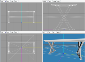
- Black mesh with AutoSmooth On.
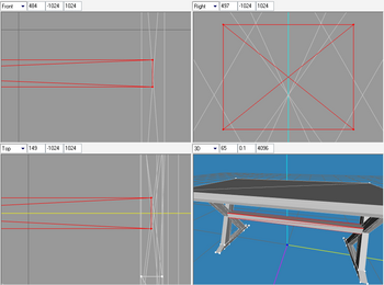
- This would mess up how it looks in-game. To correct, Select All, and check the Auto Smooth in the Smoothing Groups options in the Groups tab, then click the Clear All button. Then uncheck the Auto Smooth again to turn it off.
- Before picture and
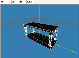
- After picture.
- This would mess up how it looks in-game. To correct, Select All, and check the Auto Smooth in the Smoothing Groups options in the Groups tab, then click the Clear All button. Then uncheck the Auto Smooth again to turn it off.
- Bones & Joints
- For the next mesh, I’ve wised up and only used Box primitives that I know how to UVmap and duplicate and mirror using Front ←→ Back and Left ←→ Right. I did not create simple boxes for legs and table top because there wouldn’t be any vertices and faces to reduce for our low-poly versions.
- Reminder:
- Keyboard shortcuts: F1-Select, F2-Move, F4-Scale
- if I use the
 button, it mostly means to do the selection in the Groups tab versus Select – means to press F1 in the Model tab or click-drag the indicated vertex/face
- Pan and zoom shortcuts in viewport:
- Keyboard shortcuts: F1-Select, F2-Move, F4-Scale


⇒ CTRL+Left-click-drag pan viewport ⇒ SHIFT+Left-click-drag controlled zoom ⇒ SHIFT+mouse-wheel faster zoom
- Creating the new top
- If you have followed along from Cycle 1 and regrouped all the groups, hide all groups except for the table "top".
- Press F1 and in the Select Options, verify we have the following settings.
- If have not done the regrouping, let’s do it now. Click-Drag the mouse over the lower vertices and ONLY these vertices of the table’s base as shown. We shall regroup this to retain for our mesh, the rest (except for the shadow – "group00") will be deleted.


- Regroup, Rename and Hide
- When you did the selection as above and
- then click Regroup – you’ll get a new group in the Groups list
- highlight the default name and
- enter "base"
- click Rename
- click Hide
- Save first as an ms3d file before we proceed (do it often)
- Use the Box primitive to create a rectangle in place of the pre-existing table "top"
- Again, use the original rectangular top to gauge table height from center of origin (where the 3 axes meet)
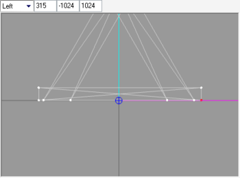
- Scale it, the result below was from using the values in the Scale Options, with y- & z-axes constrained; yours would depend on the box size that you drew
- Move it, if necessary, deselect the other axes to constrain them – it helps – and you can drag in the direction of one axis.


- Making slanted legs to form an X.
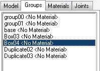
- In Groups tab, "group01"
- Hide "group01" and the top we just made – "Box03" for me.
- un-Hide the box we created before and renamed "base".
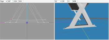
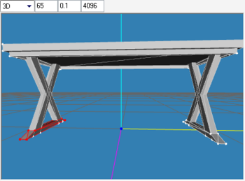
- In the Model tab, click Box or Shift+F3. Draw out a box in the Left viewport in the position shown.
- Then, Scale it and Move it so that it is flush against the base of the table (see 3D view of next pics)
-
 and Duplicate this leg, then mirror it Front ←→ Back.
- We are going to cross the legs over to make the X. Press F1 in Model tab, check your Select Options matches mine as shown
- Select the lower vertices of one leg, like so (Before pic) and then drag it over to meet the vertices of the other leg (in z-axis direction, constrain others) – see After pic.
- , Duplicate and Mirror the slanted box (Front ←→ Back).
- So, now, we have an X for legs.
- Checkpoint: my Groups list at this point.
- and
 the straight leg (mine was Box04), we don’t need it anymore.
- the boxes that form the X ("Duplicate02" & "Duplicate03" on my list), Duplicate and Mirror Left ←→ Right; resulting in a new group "Duplicate04" (pic shown in next checkpoint)
- In Groups tab,


 |
- Making a wedge for the feet of our table legs.
- OK, create another box at the foot of our x-frame legs.
- Draw as such, scale (approx .025 in my case) and Move it in position to the right side
- This pic shows mine has been scaled down and moved to the right-side-legs, but not yet positioned precisely.
- This one has been positioned (see the Front viewport) – ready for the manipulation to make it into a wedge shape. You might want to raise it slightly off the floor too (y-axis direction)
- Move vertices to make a wedge – I moved the lower outward and the upper inward along the z-axis (pink line) using the following measurements.
- Select the pair of vertices at a bottom corner.
- Then with a combination of values that fit your model, use the Move Options to move the vertices away from the center line. Choose the same values and combination of number of clicks to the other pair, so the other side is equi-distant. This is the reason I don’t use click-drag, I can never be precise enough.
- To do the other side, deselect, select other pair of vertices and move the same amount with a negative value in options
- At the end of the above step, my model looks like this. These next pics also show that I have moved the top left corner vertex to meet the leg.
- Move the upper vertices in increments of .01 (I think it took four times to make the vertices touch the leg like so).
- So, one last vertex left to do.
- When you’re satisfied with how the wedge looks
 it (in Groups tab), Duplicate and Mirror Left ←→ Right. Result of this step
- Checkpoint: Groups list after making the wedges.
- Adding a beam to the legs
- Add another box at the midpoint of the legs where the Xs meet. Mine came out to be this size. So, same drill – Scale and Move.
- It is still not precisely where I want it – at the middle (Front viewport) and center (Right viewport) of the X.
- With the beam selected, right-click on the Right/Left viewport and Frame Selection and zoom in tight (SHIFT+Left-click-drag) as shown here
- Move using the Move Options
- Checkpoint: Groups list after making the beam.
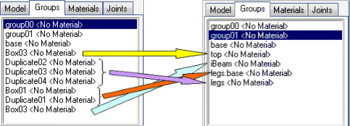
- Rename them – each group to confirm what it is and other groups as necessary. The before and after pics of renaming my groups.
- Let’s bring everything back on screen, from the Edit menu → Select None → Unhide All
- "group01" and
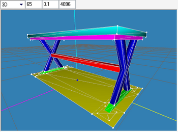
- If you right-click in 3D view and select Colored Groups, each group will have its own color.
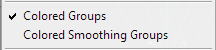
- Very useful to verify if we had Regrouped correctly
-
- The groundshadow’s size looks fine unadjusted so we shall leave that be. If you want, delete each side’s one square shadow-legs and scale the other to rectangles to match our table’s wedged "feet" shape and size.
- Assigning texture to our groups (if you forget how, instructions are here)
- Assign the main texture jpg that we created previously as a material to all groups except "group00"
- Assign the dropshadow jpg to "group00" (we can also assign the material in LithUnwrap, but the procedure is more complicated)
- Our model then, looks like this:
-
- Congratulations! We have completed our first mesh!
- Export as a file to UV-map
- Save first as an ms3d file
- select Wavefront Obj from the Export menu
- provide a suitable name and
- I’ll see you in the next section.


| |
|
TS3 HTMG SectH2 Cycle2 | |
|